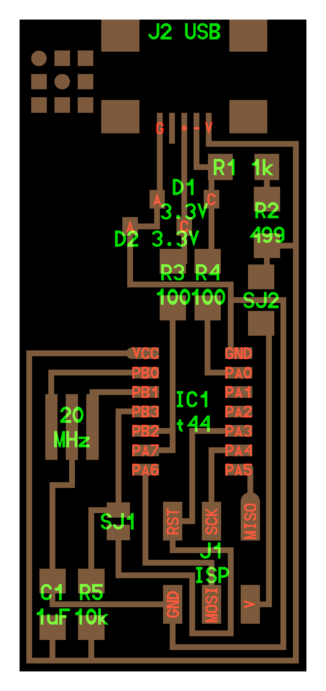
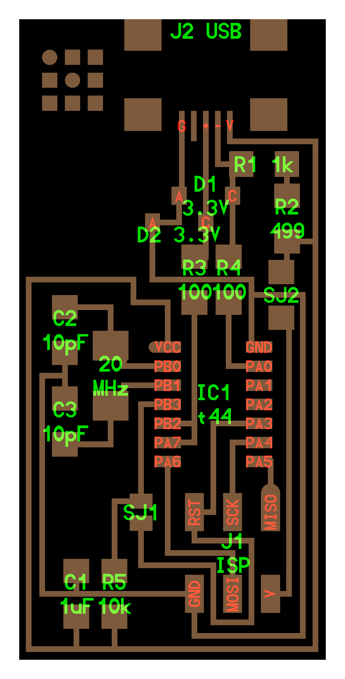
THIS IS THE 1st FABISP SCHEMATIC I WANTED TO FOLLOW
NOTE : I TRIED MANYTIMES TO PROGRAM THIS FABISP BUT I COULD NOT MAKE IT WORKS AND AFTER FINDING THAT THIS PROBLEM IS FACING MY OTHER FRIENDS ( MARC LEMAIRE AND GEOFFROI GARON-ÉPAULE ) WE DECIDED TO FOLLOW ANOTHER FABISP SCHEMATIC IN ORDER TO SPEED THE PROCESS UP AND CATCH-UP WITH THE OTHER ASSIGNMENTS

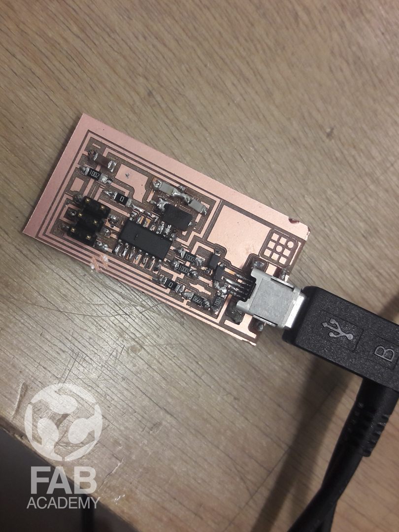
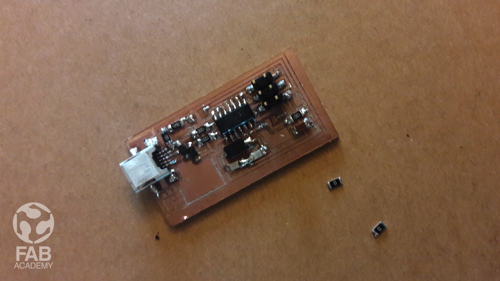
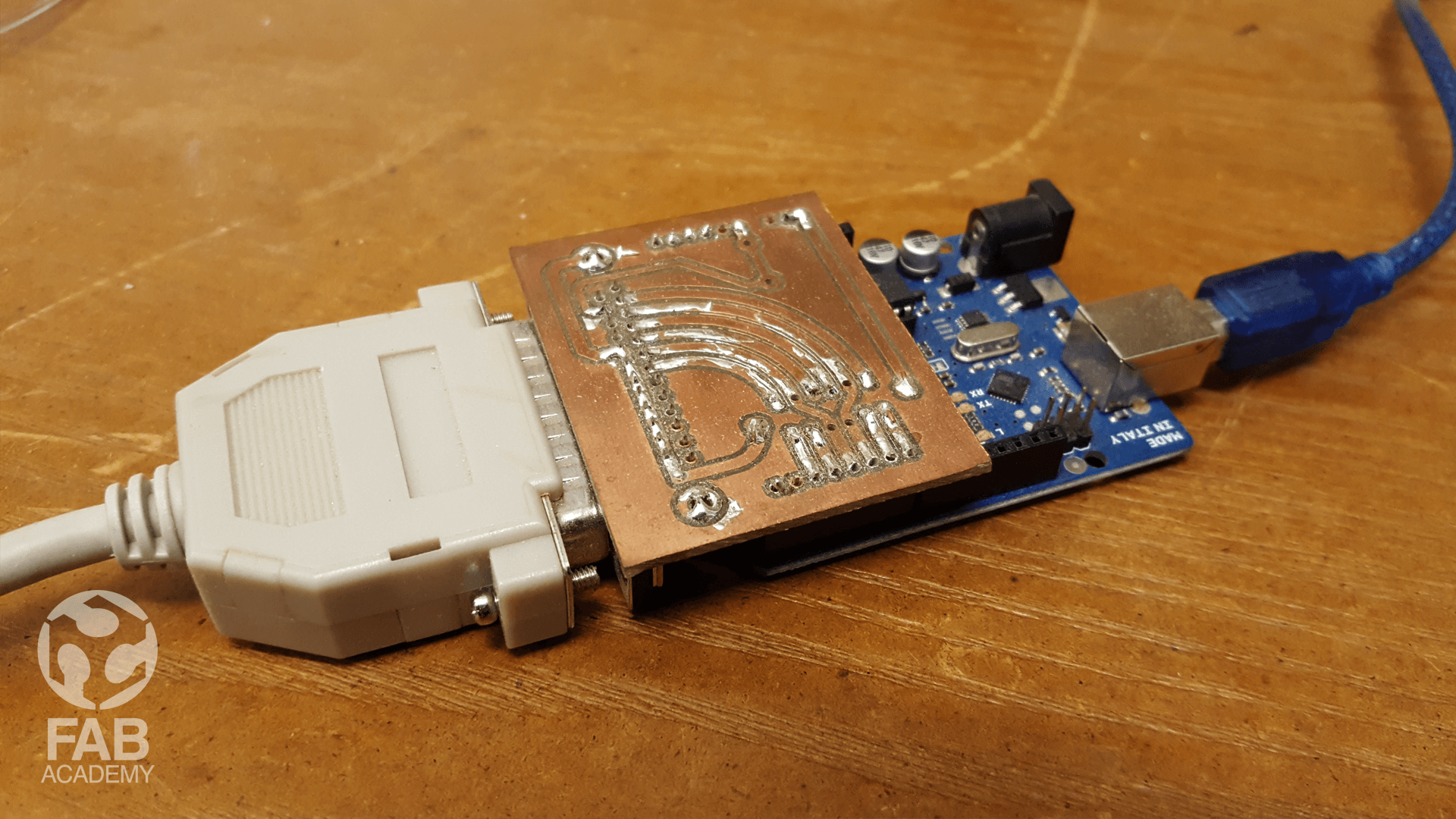
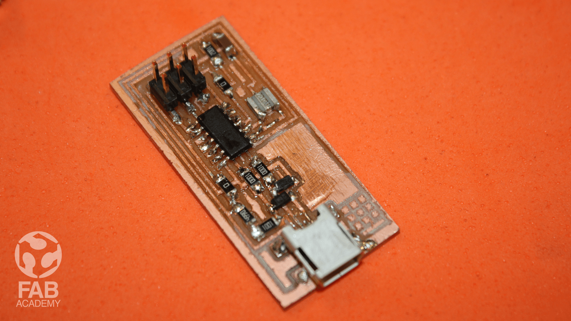
THIS IS THE 2nd FABISP I MILLED, SOLDERED AND PROGRAMMED IT WORKS PERFECTLY!
THE PROCESS
HARDWARE AND TOOLS USED:
- Fab module.
- Universal G-code sender.
- DIY CNC GRBL cnc that use GRBL CNC Shield.
1 x FR1 (Copper PCB Board).
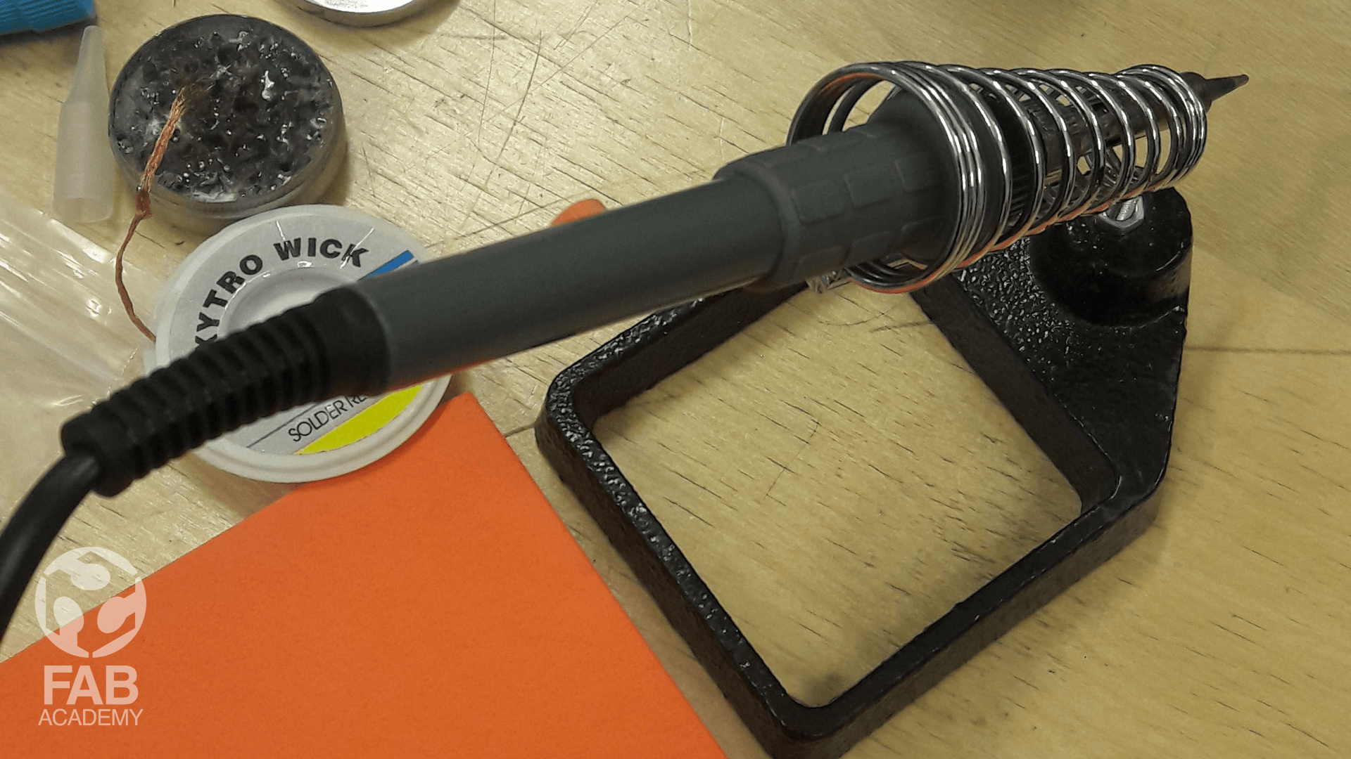
- Soldering kit ( Soldering iron,soldering wire, Solder Wick, Soldering flux, Soldering Iron stand,Vise,Solder Sucker,Tweezers )
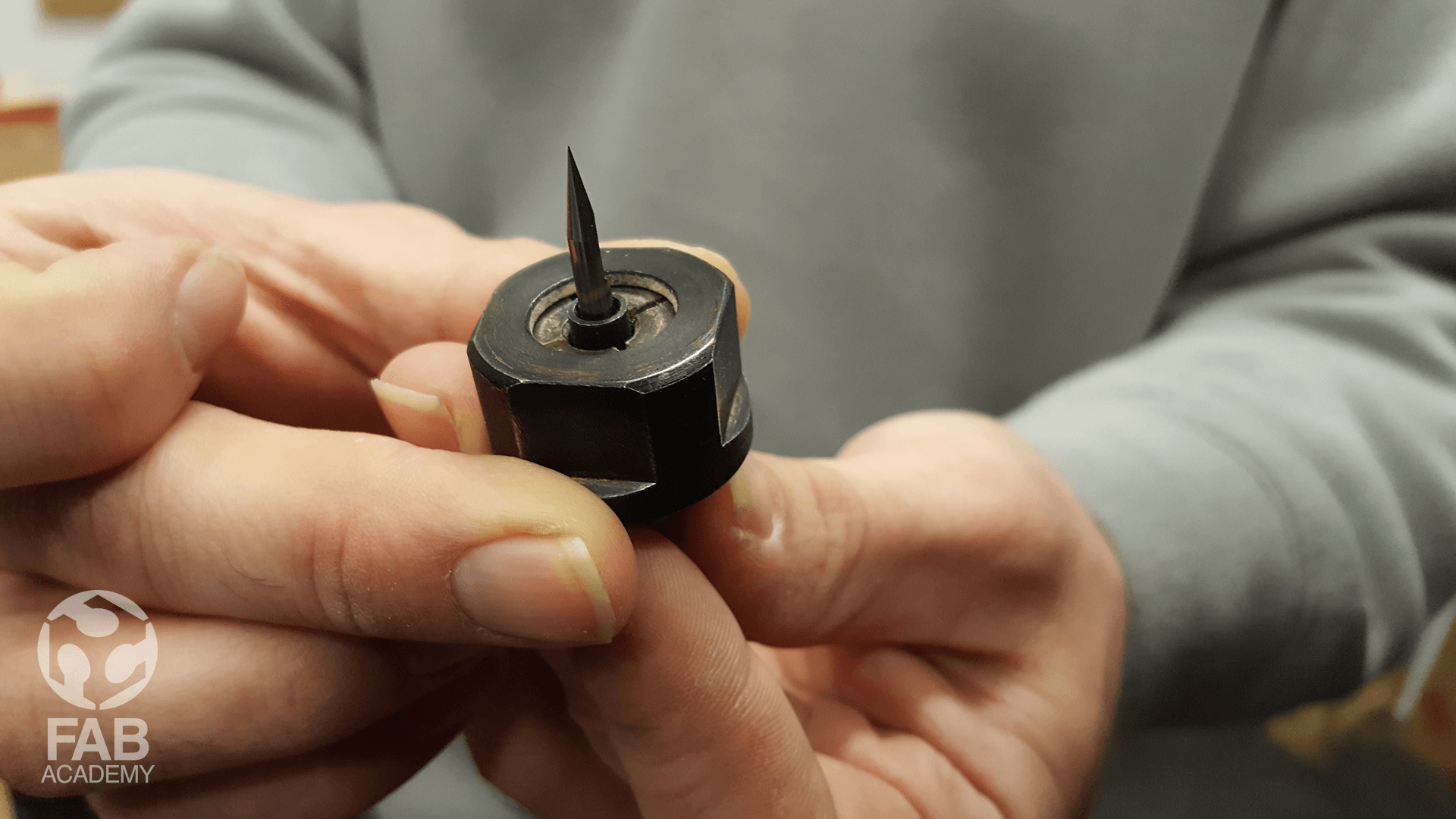
- 1 x 1/64 inch end mill bit (Titanium Coated Carbide PCB Engraving CNC Bit by 1/64 Inch Autek 10x Router Tool 30 Degree 0.1mm Tip(J3.3001Tix10) by Autek )
ELECTRONIC COMPONENTS LIST 1 X ATtiny44 ++++ ICt44 1 X 6-Pin Header ++++ J1 ISP 1 X USB Mini-B SMD ++++ Connector 1X 20 mhz smd ceramic resonator 1 X Capacitor 1uF ++++ C1 2 X Capacitor 10pF ++++ C2, C3 2 X Diode Zener 3.3V ++++ D1, D2 1 X Resistor 1k ohm ++++ R1 1 X Resistor 499 ohm ++++ R2 2 X Resistor 100 ohm ++++ R3, R4 1 X Resistor 10k ohm ++++ R5 1 X Resistor 0 ohm ++++ SJ2
- Double-Sided Tape.
- AVO multimeter.
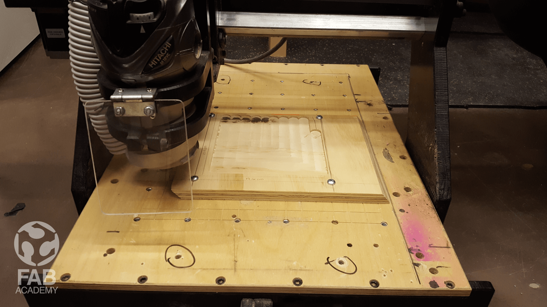
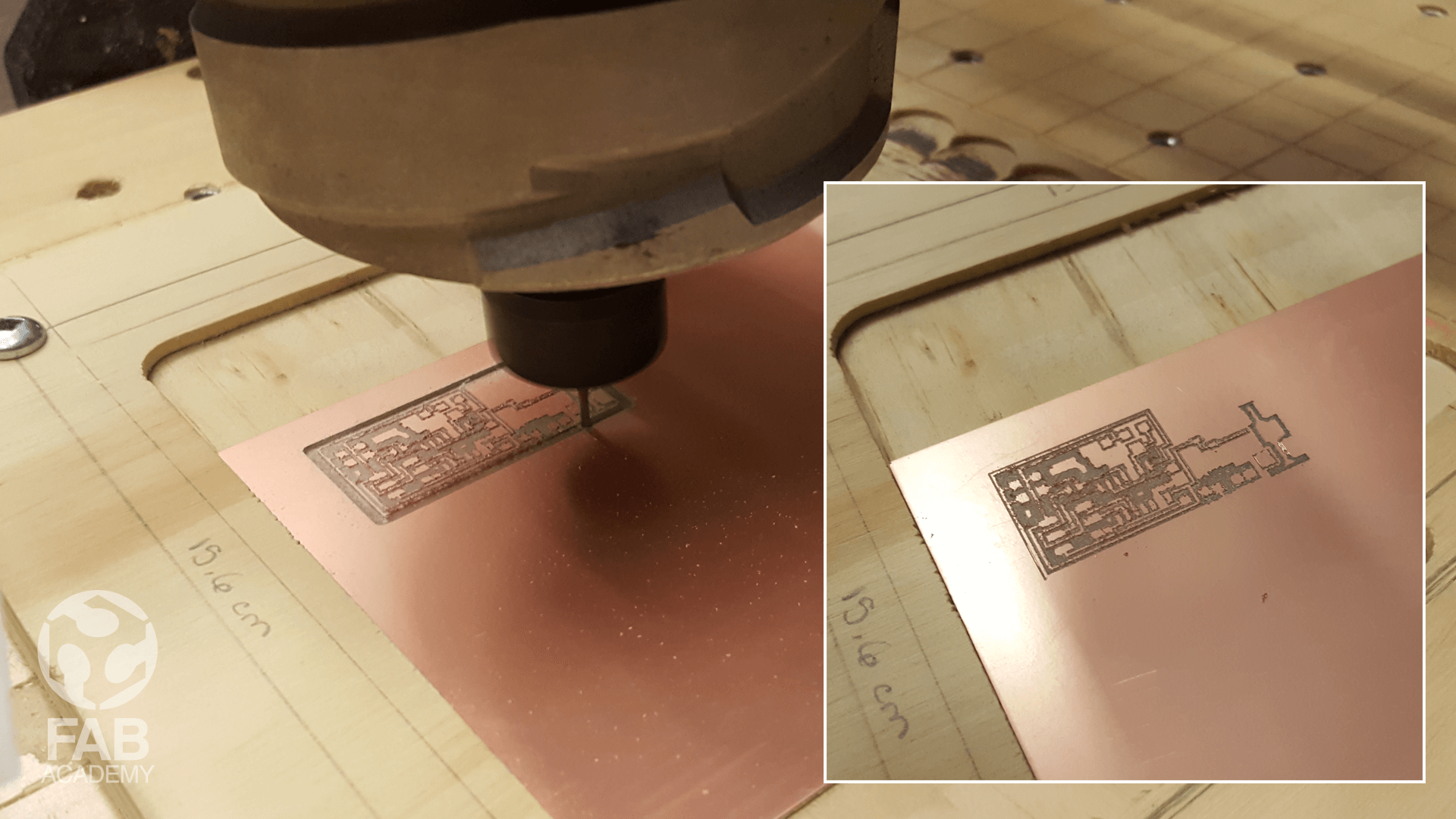
MILLING THE PCB
This week we learned about PCB fabrication. The goal was to make the FabISP AVR programmer, so we can use it as a programmer for our upcoming boards. The PCB was created by milling and not etching a copper on a board. This is a much more straightforward procedure for small volume production and it is much more safer.
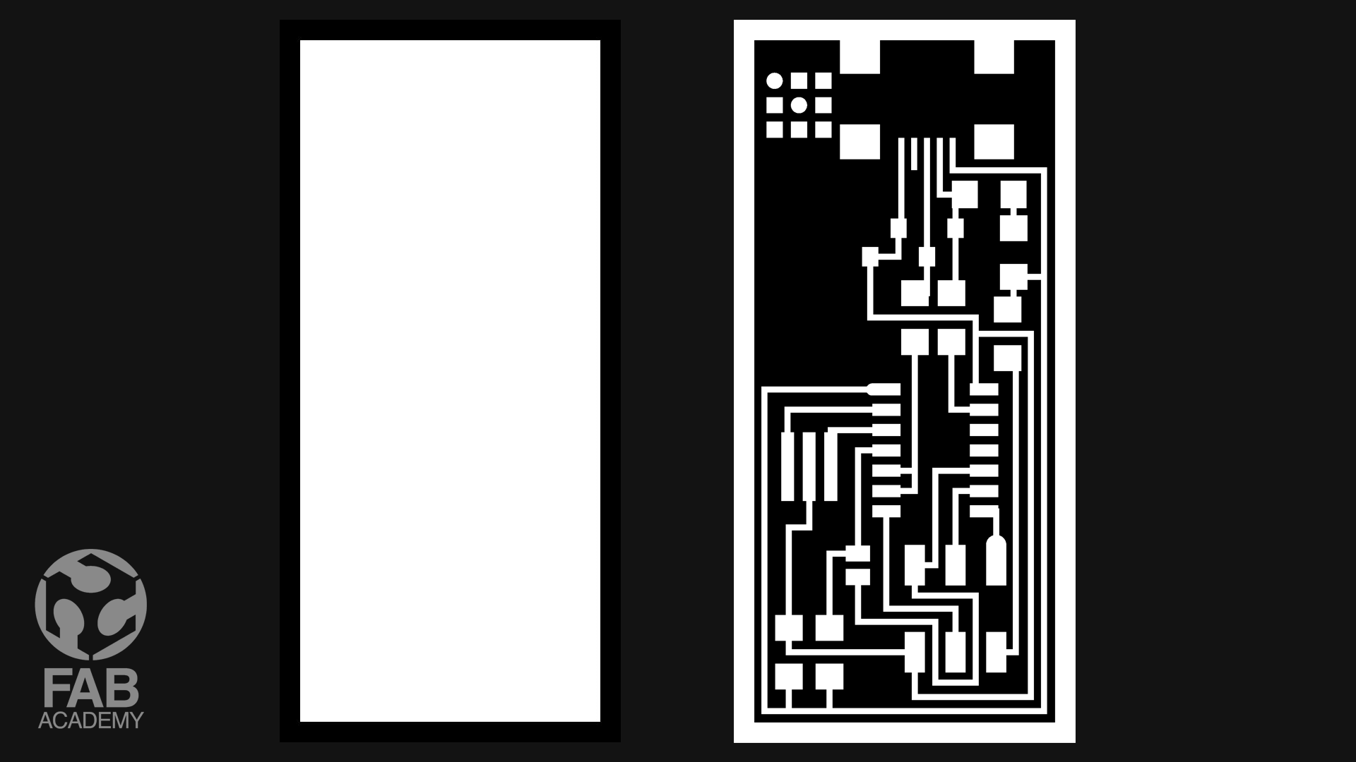
PREPARING THE FILES AND STRAT MILLING THE PCB
For milling the PCB board first I had to download the circuit traces and frame PNG files . I chose the one with the resonator . The circuit is comprised of the ATtiny44 micro-controller, a mini USB port, a 6-pin jumper and a 20MHz resonator, along with other passive and active components for current/voltage protection.
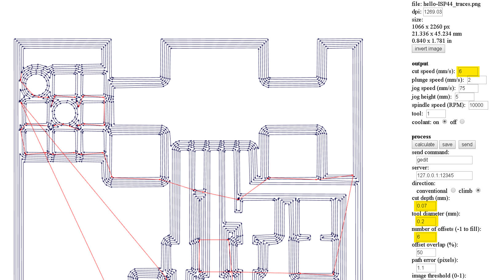
After that I had to convert the PNG files to G-code file format in order to load the G-code file in the milling machine software ( Universal G-code sender).
To convert the png files to G-code I had to use the Fab Modules.
Briefly, Fab modules provides a set of software tools for personal fabrication, intended for use with machines common to fab labs.
The setting I used for milling the PCB are highlighted in image #05
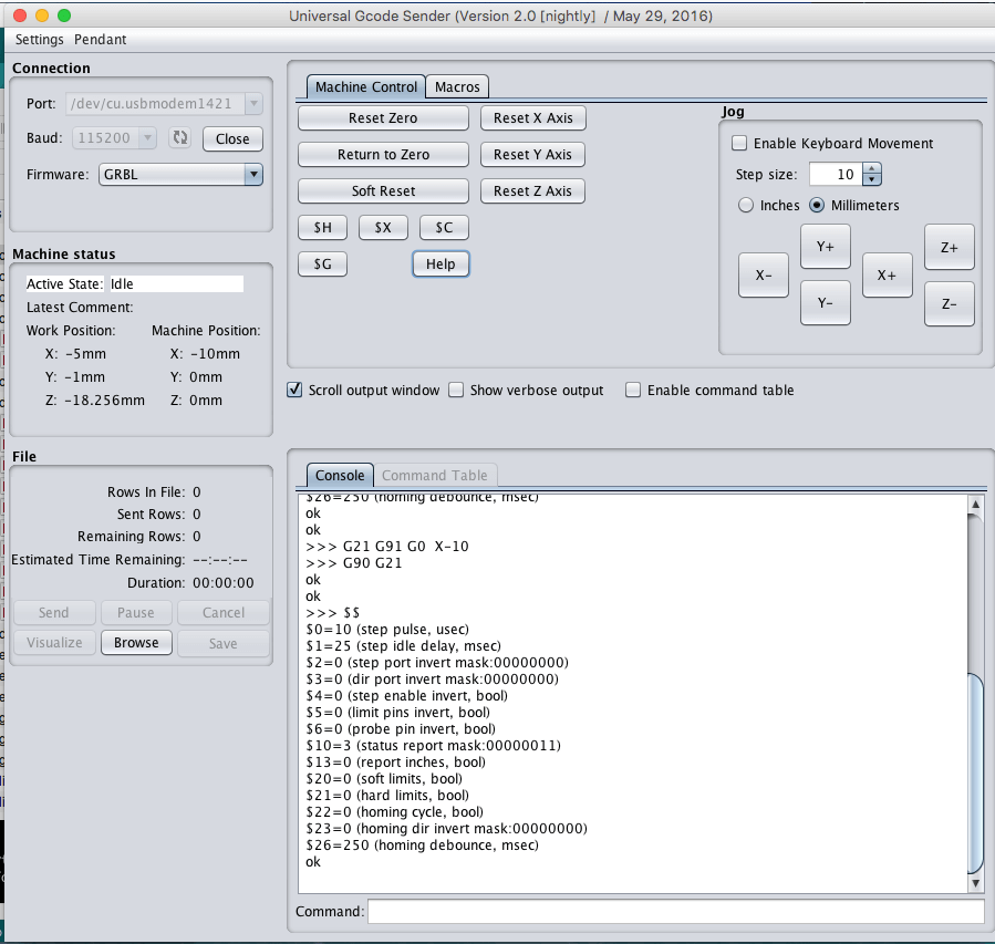
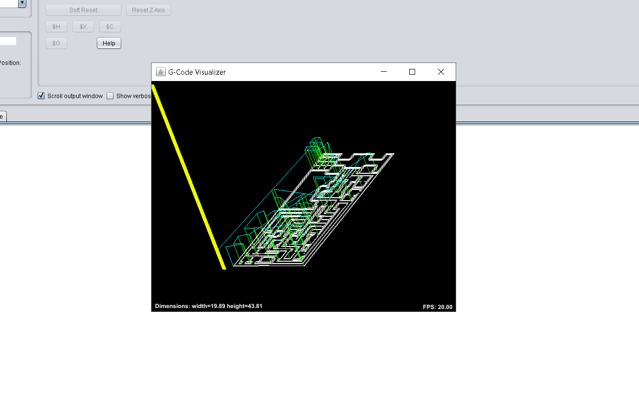
After generating the G-code file out of the png image I opened it in universal G-code sender in order to start the milling process. Universal-G-Code-Sender is a java-based, Grbl compatible cross-platform G-Code sender, available from William Winder's GitHub site.
However, universal G-code sender is an easy software to use, After downloading the software and started it, I had to connect it to the Grbl control board. I did this by selecting the correct device port number and baud rate, then I clicked on the Open button to establish connection with the CNC.
Then from the machine control menu as it is shown in image # 06 I have to specify the coordination of X,Y,Z axis so the machine can understand from which point I want to start.
Calibrating the Z-Axis was a bit time consuming processes since the machine we used doesn't have not touch plate feature so we had to zero it out manually by using paper technique this process took a lot of time and energy from us to master.
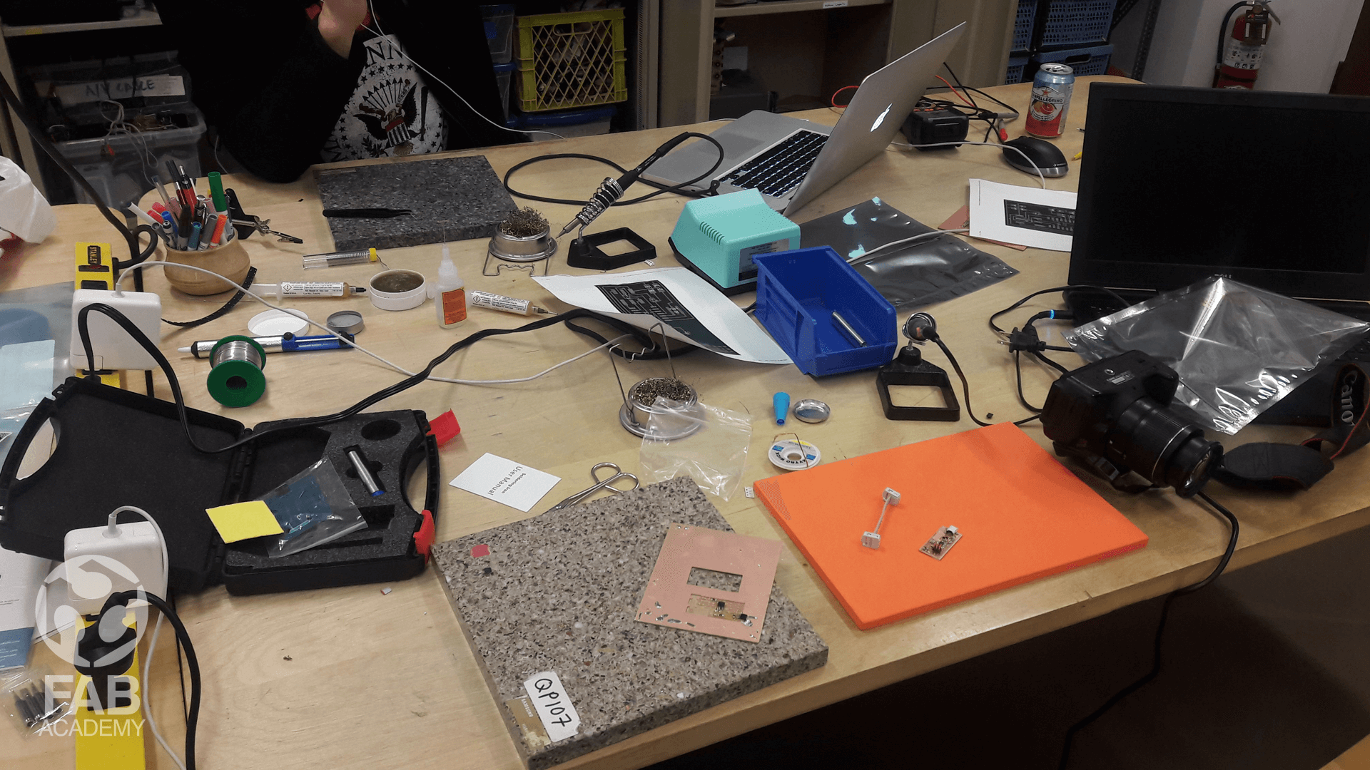
SOLDERING THE ELECTRONIC COMPONENTS
For soldering the parts I started with the hardest part to solder for me it was the ATtiny44 since it has 14 pins and they should be solder carefully and then I moved to the smallest parts
followed by the larger components however, soldering the parts was a bit tricky process for me especially I had no previous experience so after many trials and error on a scrap PCB I was confident enough
to start working on my final milled PCB board using the soldering iron.
In order to avoid overheating the components I adjusted the soldering iron heat to 300 °C it was sufficient to quickly solder the joint well without damaging them.
So after each component I was soldering I was running
a few tests using the AVO meter in order to check for short circuit current
Finlay, After spending around 4 hours soldering all the surface mount commonest I connected the board to my PC via USB cable and it passed the smoking test.
PROGRAMING THE BOARD
For programing this board I had no success at all even though I followed exactly the same tutorial mentioned in the Academy website I believe the problem was not knowing how to adjust the make file properly I was using wrong port value and knowing the port ID was about confusing at that stage because most of the tutorials I saw were targeting mac users and Linux operating system users these reasons I stopped working on this assignment in order to catch up with the other assignments.
Then, at the end of Fab Academy classes I decided to go back and work on this pending assignment however this time I chose the board that has 20000 MHZ crystal and decided to use Arduino as ISP programmer however after doing exactly the same milling and soldering process I used for my first board my new board was ready to be programed.
To start programing the revised FabISP board, I used Arduino as a programmer since it was highly recommended by my friend Alec so first after connecting Arduino to my PC I opened ISPsketch and from the tool menu I chose ArduinoISP from the programmer menu after that I uploaded the code on the Arduino board before connecting any wire to my FabISP board and then I did the wiring work using 6 male to female jumpers, The connections between my FabISP board and Arduino were as follow :
FABISP | ARDUINO BOARD
VCC = Arduino 5V
GND = GND
RST = pin 10
MOSI = pin 11
MISO = pin 12
SCK = pin 13
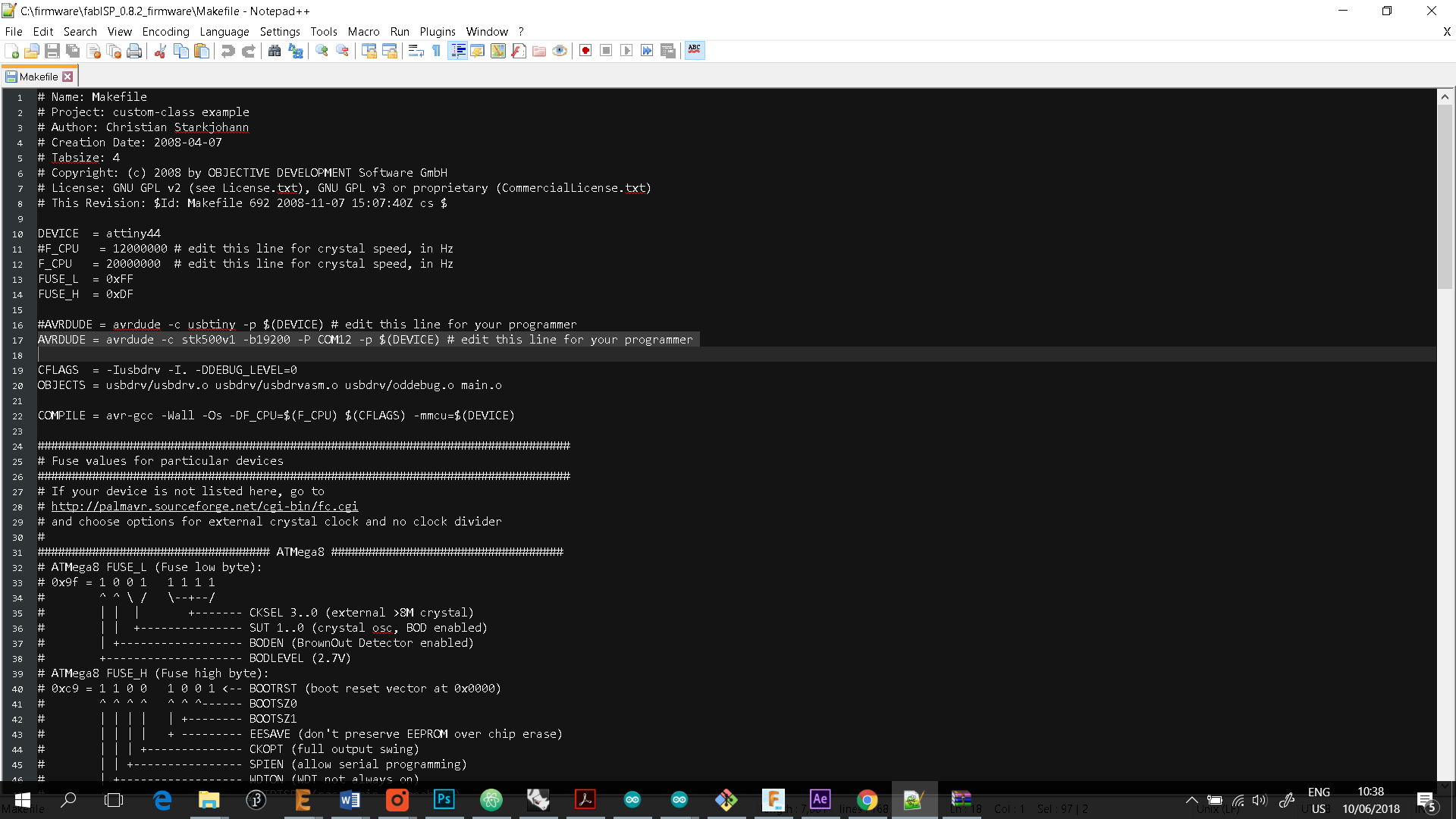
On top of that I also connected the FabISP to my computer via the mini USB cable and after I was done I opened Fab ISP firmware folder which was already installed on my pc and edited the makefile as shown in image #15
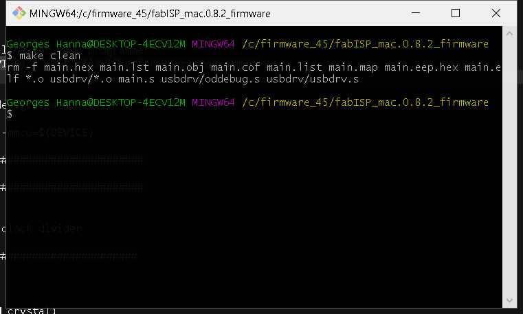
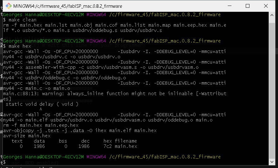
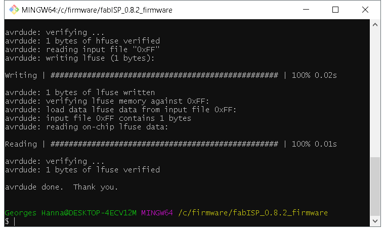
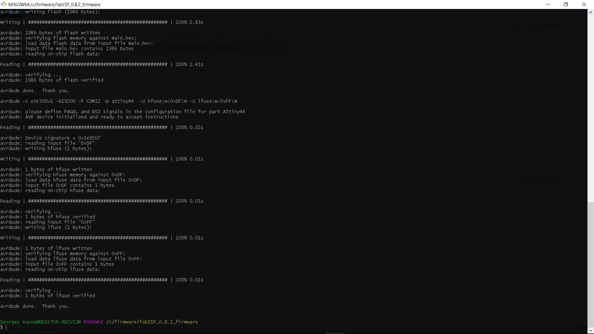
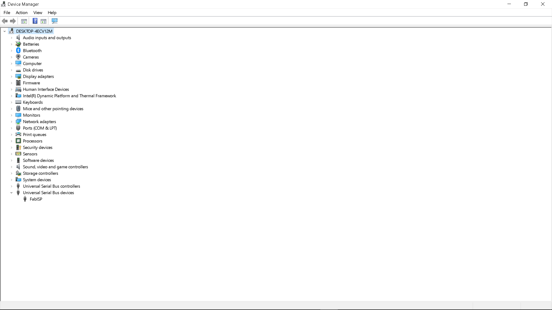
COM12 represent the port Arduino is connected to, However after that by using git windows command line I accessed Fab ISP firmware folder and type make clean and I got the massage shown in image # 16 and then I typed make hex and I got this massage shown I image # 17 and then I typed make fuse followed by make program and everything worked fine without any problem and once I got this massage shown in image # 19 knew that the program was successfully installed . Then, to check if my pc is able to detect the FabISP I removed the wiring jumpers and connect it directly to my PC and I was able to see it listed in the device manager as show in image # 20
Finally, I had to remove the lower 0 ohm jumper in to prevent any program from being uploaded to the fabISP.
In the embeed programing week I managed to use our echofab Fabisp along with other programer to program my hello world board since my Fabisp was not ready yet, you can check the process by clicking HERE.
USEFUL TIPS & LINKS
+ UNIVERSAL G-CODE SENDER BASICS HERE.
DOWNLOAD SECTION
+ hello.ISP.44.png DOWNLOAD .
+ hello-ISP44_interior.png DOWNLOAD .
+ hello-ISP44_traces.png DOWNLOAD .
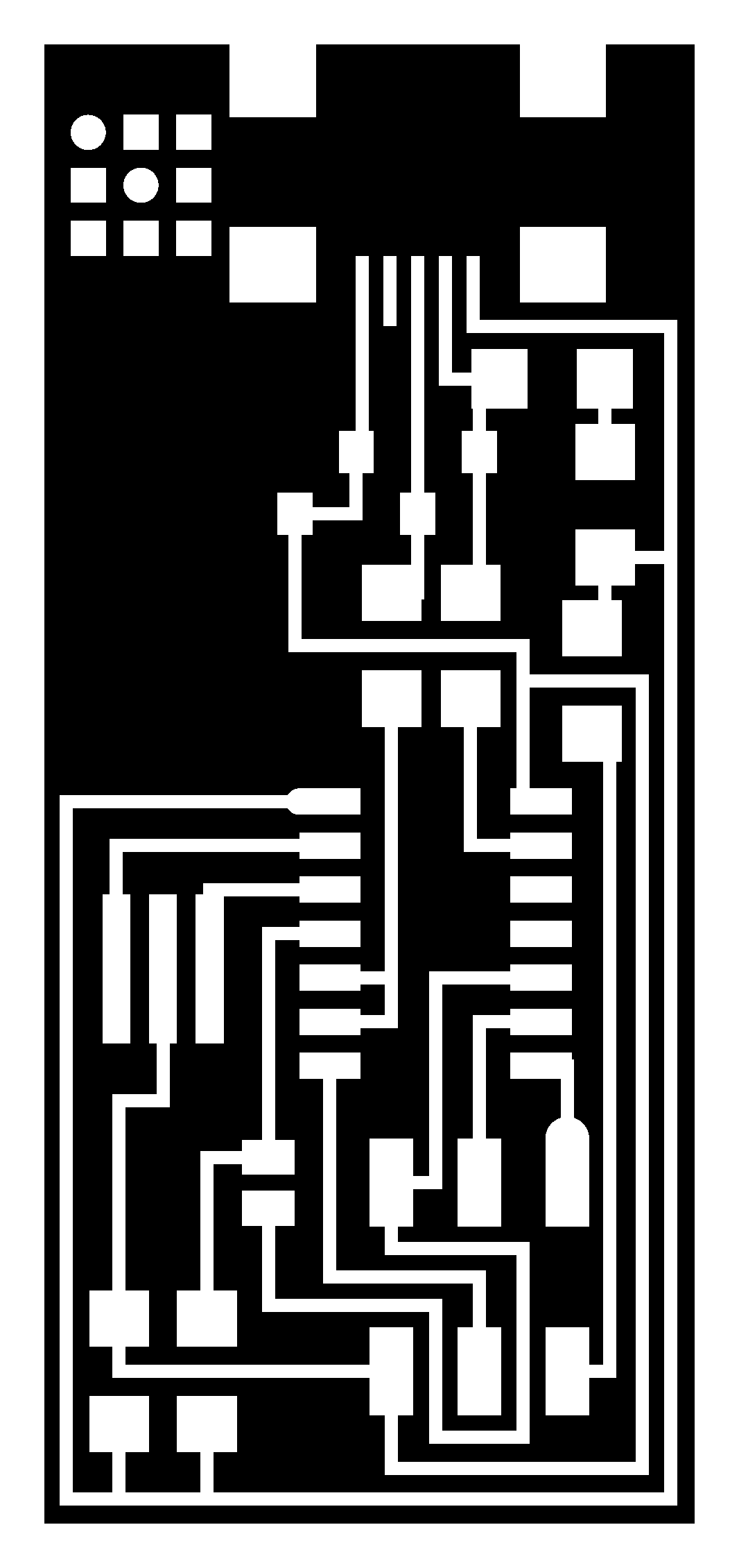